Understanding the Functionality of Axes in a Press Brake Machine
Table of Content
This post is also available in:
When comparing CNC press brakes, you will often see terms such as 3+1 axis, 4+1 axis, 6+1 axis, or 8+1 axis press brake.
But what do these axes actually control?
A CNC press brake uses several controlled axes to manage the movement of the ram, backgauge, and crowning system. Depending on the machine configuration, these axes may control bending depth, flange length, backgauge height, finger position, or machine deflection compensation.
Understanding what each axis does is more useful than simply comparing the total number of axes.
A machine with more axes provides greater backgauge automation and positioning flexibility, but it does not automatically mean that every part will be bent more accurately.
This guide explains the most common CNC press brake axes — Y1/Y2, X, X1/X2, R, R1/R2, Z1/Z2 and V — and how they are combined in different machine configurations.
What Is a CNC Press Brake Axis?
An axis is an independently controlled movement of the press brake.
The CNC controller calculates and commands these movements according to the bending program.
Different axes perform different functions:
- Y1/Y2 control ram position and bending depth.
- X controls the front-to-back position of the backgauge.
- R controls backgauge height.
- Z1/Z2 control the lateral position of the backgauge fingers.
- V controls CNC crowning compensation.
More advanced backgauges may also use X1/X2 and R1/R2, allowing the two sides of the backgauge to be positioned independently.
The correct axis configuration therefore depends mainly on the geometry of the parts being produced and how much automatic backgauge positioning is required.
CNC Press Brake Axes at a Glance
| Axis | What It Controls | Main Function |
|---|---|---|
| Y1 / Y2 | Left and right ram position | Controls bending depth and ram synchronization |
| X | Backgauge front/rear position | Determines flange length |
| X1 / X2 | Independent backgauge depth | Allows different gauging depths on the left and right |
| R | Backgauge vertical position | Adjusts finger height |
| R1 / R2 | Independent finger height | Provides more flexible vertical positioning |
| Z1 / Z2 | Left/right finger position | Automatically positions the two fingers laterally |
| V | Crowning system | Compensates for machine deflection during bending |
Each of these movements solves a different positioning problem. This is why simply saying that one machine has “more axes” does not fully describe its capability.
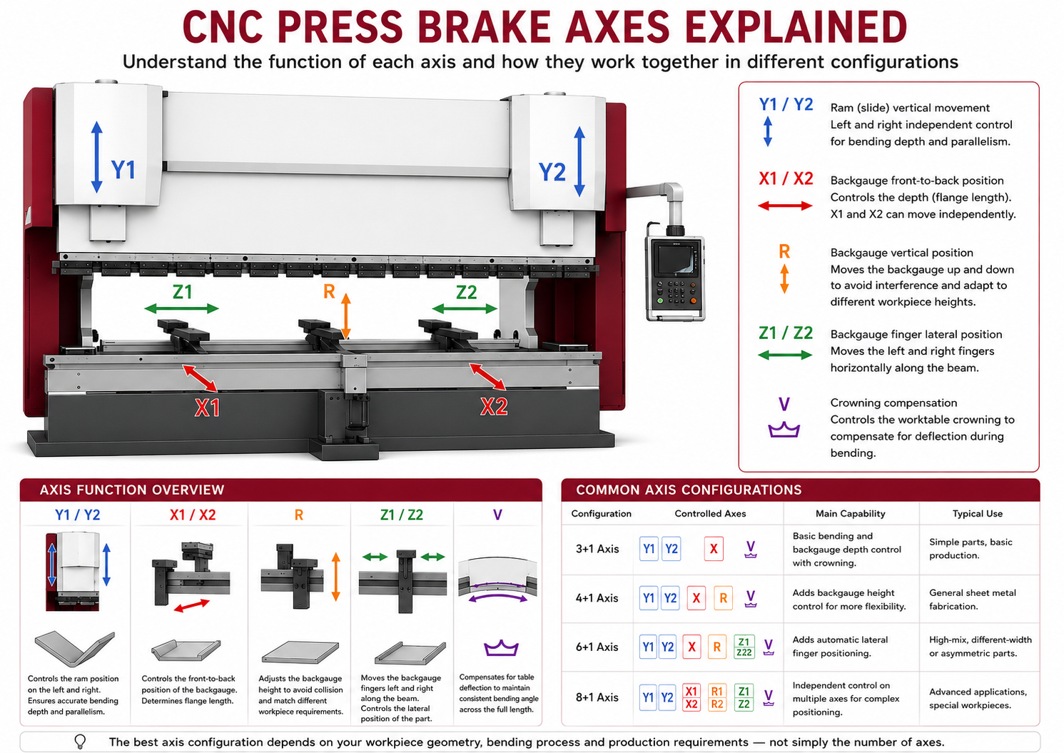
Y1 and Y2 Axes — Ram Positioning
On a CNC servo-hydraulic press brake, the ram is normally controlled independently on the left and right sides.
These two controlled positions are referred to as:
Y1 — left side of the ram
Y2 — right side of the ram
During bending, the CNC system continuously controls the position of both sides of the ram.
This allows the machine to maintain synchronized movement and accurately control the final bending depth.
Because bending depth directly affects the resulting bending angle, Y1/Y2 control is one of the most important parts of an electro-hydraulic CNC press brake.
What Y1/Y2 mainly control
- Ram position
- Bending depth
- Left/right synchronization
- Repeatability of the programmed ram position
However, Y1/Y2 alone do not determine final bending accuracy.
Machine frame rigidity, hydraulic control, position feedback, tooling condition, material thickness, crowning compensation and material consistency also influence the final bending result.
X Axis — Backgauge Depth
The X axis controls the front-to-back movement of the backgauge.
Its primary purpose is to determine where the sheet is positioned before bending.
In practical terms, the X-axis position largely determines the flange dimension.
For example, if a part requires a 50 mm flange, the CNC system calculates the appropriate backgauge position and moves the X axis to the programmed location.
The operator then pushes the sheet against the backgauge fingers before starting the bend.
X-axis control is important for:
- Flange length
- Repetitive positioning
- Multi-step bending
- Batch production
- Reducing manual measurement
For most general-purpose CNC press brakes, a single X axis moves the backgauge assembly forward and backward.
X1 and X2 Axes — Independent Backgauge Depth
An advanced backgauge may separate the normal X movement into:
X1 — left-side depth positioning
X2 — right-side depth positioning
Instead of moving both sides of the backgauge to exactly the same depth, X1 and X2 can be controlled independently.
This is useful when the two reference points of the workpiece cannot be positioned on the same straight line.
Possible applications include:
- Tapered parts
- Irregular workpieces
- Parts requiring different left and right gauging depths
- Specialized multi-step bending operations
X1/X2 should therefore not be confused with the standard X axis.
A machine described as having an X axis does not automatically have independent X1/X2 positioning.
R Axis — Backgauge Height
The R axis moves the backgauge fingers vertically.
Instead of remaining at one fixed height, the CNC system can raise or lower the backgauge according to the bending program.
This becomes useful when:
- A previously bent flange would interfere with the backgauge
- Different reference heights are required
- The workpiece geometry changes during a multi-step bending sequence
- The operator needs to position the fingers at a more suitable height
For general sheet-metal production, combining X and R provides considerably more positioning flexibility than an X-only backgauge.
This is one reason why Y1, Y2, X and R + V is a common general-purpose CNC press brake configuration.
R1 and R2 Axes — Independent Vertical Positioning
On more advanced backgauge systems, the vertical movement can also be separated into:
R1 — left finger vertical positioning
R2 — right finger vertical positioning
This allows the two sides of the backgauge to operate at different heights.
R1/R2 is not necessary for most conventional sheet-metal parts, but it can provide additional positioning flexibility for unusual or demanding workpieces.
As with X1/X2, the important distinction is independence.
A standard R axis moves the relevant backgauge structure together, while R1/R2 provide separate controlled movements.
Z1 and Z2 Axes — Lateral Backgauge Finger Positioning
The Z axes control the left-to-right position of the backgauge fingers along the bending length.
They are normally divided into:
Z1 — one backgauge finger
Z2 — the other backgauge finger
With CNC-controlled Z1/Z2 axes, the machine can automatically change the distance and position of the two fingers according to the bending program.
Without Z1/Z2, operators can still reposition the fingers laterally, but this adjustment is normally performed manually.
Z1/Z2 are particularly useful when:
- Part widths change frequently
- Different reference positions are required
- Asymmetrical parts are produced
- Operators frequently move the backgauge fingers between jobs
- Production involves many different part types
- Setup time needs to be reduced
This is the main practical difference between many 4+1 and 6+1 axis press brake configurations.
A 6+1 axis machine does not automatically apply more bending force or produce a more accurate ram position simply because Z1/Z2 are included.
The main benefit is greater backgauge automation and reduced manual finger repositioning.
V Axis — CNC Crowning Compensation
During bending, both the press brake frame and tooling system experience elastic deflection under load.
This deflection can cause a long workpiece to bend slightly differently in the center compared with the two ends.
A crowning system compensates for this effect.
In MECA’s axis notation, the “+1” refers to the CNC-controlled V-axis crowning system.
For example:
4+1 axis = Y1 + Y2 + X + R + V
6+1 axis = Y1 + Y2 + X + R + Z1 + Z2 + V
The CNC system adjusts the crowning according to the bending conditions to help maintain a more consistent bending angle across the working length.
Crowning becomes particularly important when bending:
- Long workpieces
- Thicker materials
- Parts requiring consistent angles across the full bending length
What Does “+1” Mean in a Press Brake Axis Configuration?
This terminology can cause confusion because press brake manufacturers do not always count axes in exactly the same way.
For MECA CNC press brakes, the +1 represents the V-axis crowning system.
Therefore:
3+1 Axis
Y1 + Y2 + X + V
Provides CNC ram control, backgauge depth positioning and crowning compensation.
4+1 Axis
Y1 + Y2 + X + R + V
Adds CNC-controlled vertical movement of the backgauge.
This is a practical general-purpose configuration for many sheet-metal fabrication applications.
6+1 Axis
Y1 + Y2 + X + R + Z1 + Z2 + V
Adds automatic lateral positioning of the two backgauge fingers.
This configuration is useful when finger positions need to change frequently between parts or bending steps.
8+1 Axis
One possible advanced configuration is:
Y1 + Y2 + X1 + X2 + R1 + R2 + Z1 + Z2 + V
This provides independent positioning on multiple backgauge movements and is intended for applications requiring more complex gauging.
Common CNC Press Brake Axis Configurations
| Configuration | Typical Axes | Main Capability |
| 3+1 Axis | Y1, Y2, X + V | Basic CNC bending and backgauge depth control |
| 4+1 Axis | Y1, Y2, X, R + V | General-purpose CNC bending with vertical backgauge positioning |
| 6+1 Axis | Y1, Y2, X, R, Z1, Z2 + V | Adds automatic lateral positioning of both backgauge fingers |
| 8+1 Axis | Y1, Y2, X1, X2, R1, R2, Z1, Z2 + V | Advanced independent backgauge positioning |
These descriptions should be treated as configuration examples rather than universal naming rules.
When comparing press brakes from different manufacturers, always check the actual controlled axes listed in the machine specification instead of comparing only labels such as “4-axis” or “6-axis.”
Does a Press Brake With More Axes Bend More Accurately?
Not necessarily.
This is one of the most common misunderstandings when comparing CNC press brakes.
Adding Z1/Z2, X1/X2 or R1/R2 mainly increases the flexibility and automation of the backgauge.
For example, changing from 4+1 to 6+1 axes mainly adds CNC-controlled lateral movement of the two backgauge fingers.
It does not fundamentally change the Y1/Y2 ram control system.
Bending accuracy depends on the complete machine system, including:
- Frame rigidity
- Y1/Y2 position control
- Position feedback
- Hydraulic or servo drive performance
- Crowning compensation
- Tooling accuracy
- Material thickness and consistency
- CNC parameter settings
Therefore, the best axis configuration is not always the configuration with the highest number of axes.
It is the configuration that matches the actual positioning requirements of the parts you produce.
Which CNC Press Brake Axis Configuration Do You Need?
For many standard sheet-metal applications, 4+1 axes provide a practical balance between automation, flexibility and machine cost.
If the workpieces are mainly regular panels, cabinets, boxes, trays and similar products, and the two backgauge fingers rarely need to move laterally, Z1/Z2 may provide limited additional benefit.
A 6+1 axis configuration becomes more useful when production involves:
- Frequent product changeovers
- Different-width workpieces
- Asymmetrical parts
- Frequently changing gauging positions
- Repeated manual movement of backgauge fingers
More advanced configurations such as X1/X2 or R1/R2 should be selected only when the part geometry and bending sequence actually require independent backgauge positioning.
If you are specifically deciding between these two common configurations, read our 4+1 Axis vs 6+1 Axis Press Brake: Which Is Right for You? guide for a detailed application-based comparison.
Frequently Asked Questions
What are the main axes of a CNC press brake?
The most common axes are Y1/Y2 for ram positioning, X for backgauge depth, R for backgauge height, Z1/Z2 for lateral finger positioning and V for crowning compensation. Advanced backgauges may also use X1/X2 and R1/R2.
What is the difference between a 4+1 and 6+1 axis press brake?
In a typical MECA configuration, a 4+1 axis machine uses Y1, Y2, X and R plus V crowning. A 6+1 axis configuration adds Z1 and Z2, allowing the two backgauge fingers to move laterally under CNC control.
Does a 6+1 axis press brake provide better bending accuracy?
Not inherently. Z1/Z2 mainly improve backgauge positioning flexibility and automation. Actual bending accuracy depends on the ram control system, machine frame, feedback system, crowning, tooling, material and other factors.
What does the “+1” mean?
In MECA press brake configurations, the +1 refers to the CNC crowning or V axis.
Do I need Z1 and Z2 axes?
Z1/Z2 are valuable when operators frequently need to reposition the two backgauge fingers laterally. If your finger positions remain mostly fixed, a 4+1 axis configuration may already meet your production requirements.
Is an 8+1 axis press brake always better?
No. Additional axes provide more independent positioning capability, but they also add machine complexity and cost. The correct configuration should be selected according to the workpiece geometry and bending process rather than the axis count alone.
Choose the Axis Configuration Based on Your Parts
The number of CNC axes should follow the requirements of the workpiece — not simply the idea that more axes are always better.
For standard sheet-metal production, a 4+1 axis configuration can already provide effective CNC control.
For production involving frequent changes in backgauge finger positions, asymmetrical parts or high-mix jobs, adding Z1/Z2 through a 6+1 axis configuration can reduce manual setup and improve production flexibility.
For more demanding applications, independent X1/X2 or R1/R2 positioning can provide additional backgauge capability.
Not sure which configuration your parts require?
Send MECA your part drawing and bending requirements. Our engineers can review the bending sequence and backgauge positioning requirements and recommend an appropriate CNC axis configuration.