How to Choose the Right Deflection Compensation for Your CNC Press Brake
Table of Content
This post is also available in:
Español (Spanish) العربية (Arabic) Русский (Russian)
How to Choose the Right Deflection Compensation for Your CNC Press Brake
Press Brake Deflection compensation is the single most critical factor in preventing the “Canoe Effect” in sheet metal bending. If you are looking to improve your CNC press brake accuracy, understanding the nuances of deflection compensation is more important than raw tonnage. Whether you utilize hydraulic or mechanical systems, choosing the right deflection compensation technology based on your specific production needs is key.
Why Deflection Compensation is Essential for Bending Accuracy
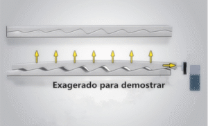
A CNC press brake is an important piece of equipment in sheet metal processing, and its working accuracy directly affects the bending precision of the workpiece. During the bending process, the press brake experiences the greatest force at both ends of the slider. The reaction force from the material bending causes the lower surface of the slider to deform into a concave shape. The deformation is most pronounced in the middle part of the slider, causing the final bending angle of the workpiece to vary across the entire length.
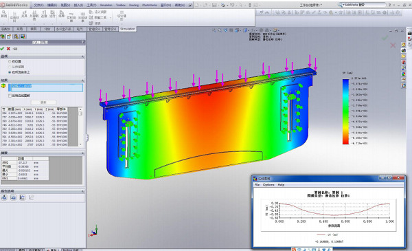
To eliminate the adverse effects caused by slider deformation, it is necessary to compensate for the deflection deformation of the slider. Common compensation methods include hydraulic compensation and mechanical compensation. Both methods create an upward elastic deformation in the middle of the worktable to counteract the deformation of the machine’s slider. This ensures the accuracy of the processing joint surfaces and improves the overall precision of the workpiece.

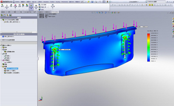
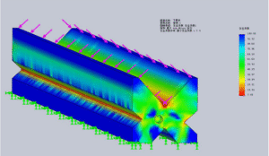
Mold Safety Factor Analysis Chart
- Hydraulic Crowning System
- Mechanical Crowning System
Scenario 1: Hydraulic Deflection Compensation for High-Volume Versatility
Who is this for? Workshops processing hundreds of parts daily, frequently switching between material thicknesses (e.g., 2mm to 6mm) and types (Aluminum, Steel).
-
The Problem: Manual setup takes too long, killing efficiency.
-
The Solution: Hydraulic Deflection Compensation.
-
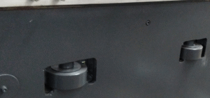
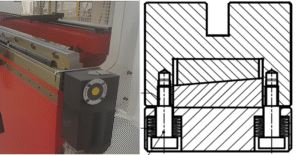
How it Works: This system uses hydraulic cylinders embedded in the lower worktable. Based on the CNC data, it creates an upward “neutral plate bulging” utilizing the elastic deformation of the steel plate itself.
-
Why Choose It: It offers automatic deflection compensation that adjusts in real-time. While it is sensitive to oil temperature changes, it provides the speed and versatility needed for general-purpose fabrication.
-
Best For: Workshops prioritizing speed and versatility for standard precision tasks.
Summary: Which Deflection Compensation Fits You?
| Feature | Hydraulic Compensation | Standard Mechanical | Bi-directional Mechanical |
| Adjustment | CNC Automatic | CNC / Manual | CNC Automatic Motor |
| Stability | Moderate (Oil Temp) | High | Maximum (Interlocking) |
| Repeatability | Standard | Good | Zero Error |
| Best For | Speed & Efficiency | General Precision | High-End / Long Parts |
Final Verdict
To prevent bending errors, you must choose a press brake deflection compensation method that aligns with your specific goals.
-
Choose Hydraulic for speed.
-
Choose Manual for low cost.
-
Choose Bi-directional Mechanical Crowning for the ultimate stability and precision on high-value projects.